Last update. July 30th 2024
Johann Felipe Gonzalez – johannavila@cmail.carleton.ca
About this project
We aim to facilitate the design process and user experience in programming-based CAD by introducing bidirectionnal programming features. We present our modified versions of OpenSCAD including different interactive features to enhance the experience in this application.
We present two projects. First, we present a modified version of OpenSCAD where we have integrated navigation and editing through interactions with the view. In our second project, our modified version of OpenSCAD includes interactive features to facilitate the creation of parametric models.
Bidirectional Programming in Constructive Solid Geometry-Based CAD
We present our Bidirectional Programming version of OpenSCAD. We have integrated navigation and editing through interactions with the view.
Getting started
This project is currently supported only for MacOS. You can download the latest binaries of our version on this link. Also, it works well in ONE file models.
Start the application
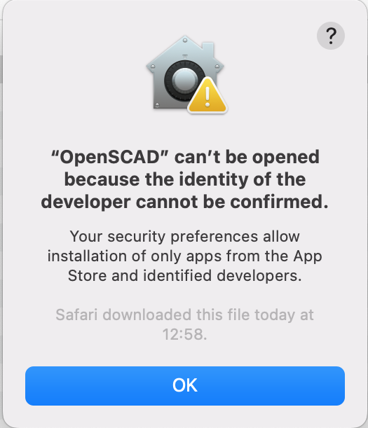
This version of OpenSCAD is under development and it does not have a Developer ID certificate. Thus, when you try to run it, a warning message indicates that the system can not open the application because it cannot confirm the developer’s identity (Fig. 1).
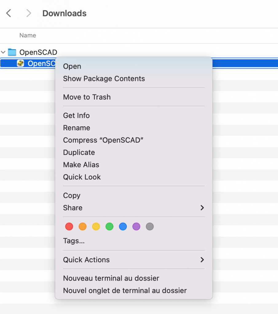
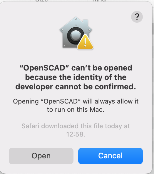
You can do a secondary click (typically a two fingers tap or a right click). The system will display an options list. Select the option “Open” (Fig. 2). A pop-up will appear asking for confirmation of this action. Confirm by pressing the “Open” button.
You will see the normal OpenSCAD interface.
Bidirectional Programming Features
We have implemented two sets of features: Navigation and Editing. Please activate both features before start
Activating
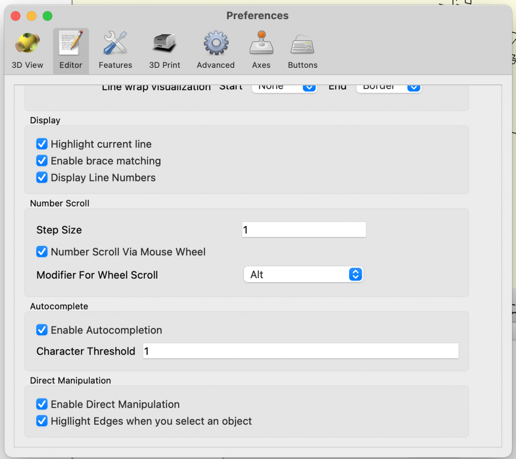
Typically, the settings for editing from the view are set by default. You should see at the bottom of the View Area three new buttons: Translate, Rotate, and Scale. If not, go to settings -> editor. Scroll down and find the options “Enable direct manipulation” and “Highlight Edges when you select an object”. Check them. If they are already checked, uncheck them, and recheck them. The system should have placed the buttons previously mentioned in the view area.
Navigation
We developed a series of features to assist users in understanding how the code is related to the elements in the view.
Reverse search
The original version of OpenSCAD allows right-clicking on the view elements to display a list of the code statements contributing to creating that part. In our OpenSCAD version, when you hover over the different items on the list, the system will mark that element as the target. The program colors green the edges of the target. It also highlights the code statement, including its scope, that creates the target in the same color. The system highlights in green the code statements of the call stack involved in the target. It adds a number on the editor’s margins to follow the target’s stack order.
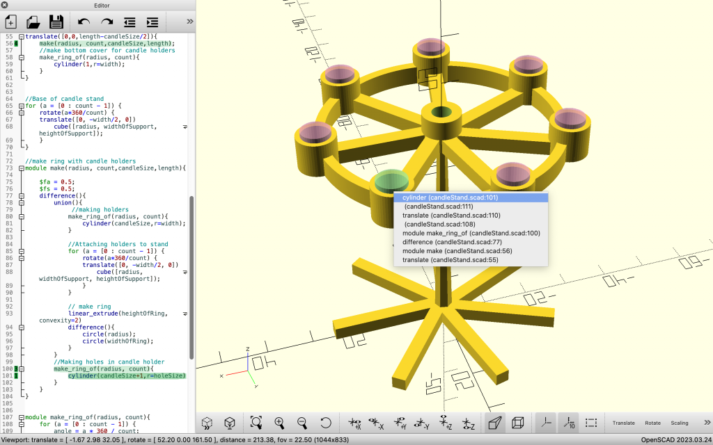
Suppose the code statement of the target creates other elements in the view (for instance, a code statement inside a loop or in a module instantiated several times). In that case, these elements are marked as impacted. The system colors pink the edges of impacted elements in the view. Consequently, the code statements in the editor are colored pink. If the target part is created by a difference or an intersect statement, the system adds colored ghosts of the removed part in the target and impacted elements. The user can now right-click on the ghost to explore their code, just like the other parts.
Forward search
The user can also search elements from the code editor. By selecting at least two text characters and pressing the key F1, the system will locate the parts in the view created by the code statement. If only one, the system will mark the part as the target. Otherwise, all elements will be marked as impacted. If the user selects the text of variable definitions, the system will find all the elements impacted by the variable and will mark the impacted. The system will color the edges, create ghosts, and highlight the code, as it is described in the reverse search.
Editing
The system allows users to perform some edits directly from the view.
Performing edits
To edit the view, you must first select the element you want to edit. You can do it by marking an element as a target using the Reverse search feature explained previously. Then, you can select between the three available buttons to perform the spatial edits of Translate, Rotate, and Scale.
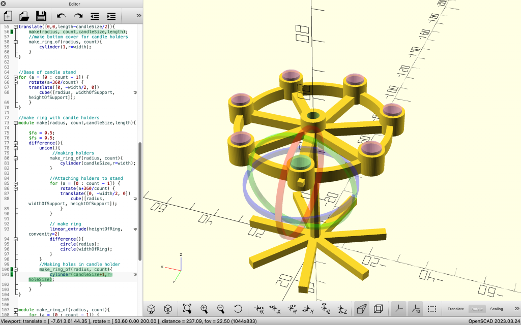
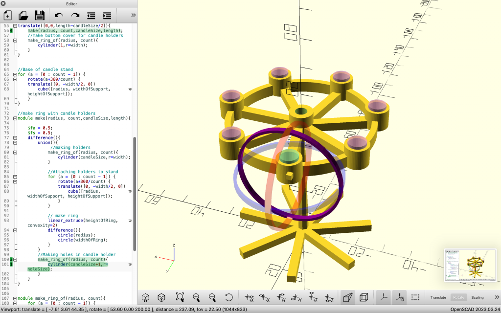
After clicking, the system places a widget representing the three axes (X,Y, and Z) in the center of the target object. You must select the axis you want to edit by clicking on it. The widget will turn opaque purple, indicating you are in editing mode.
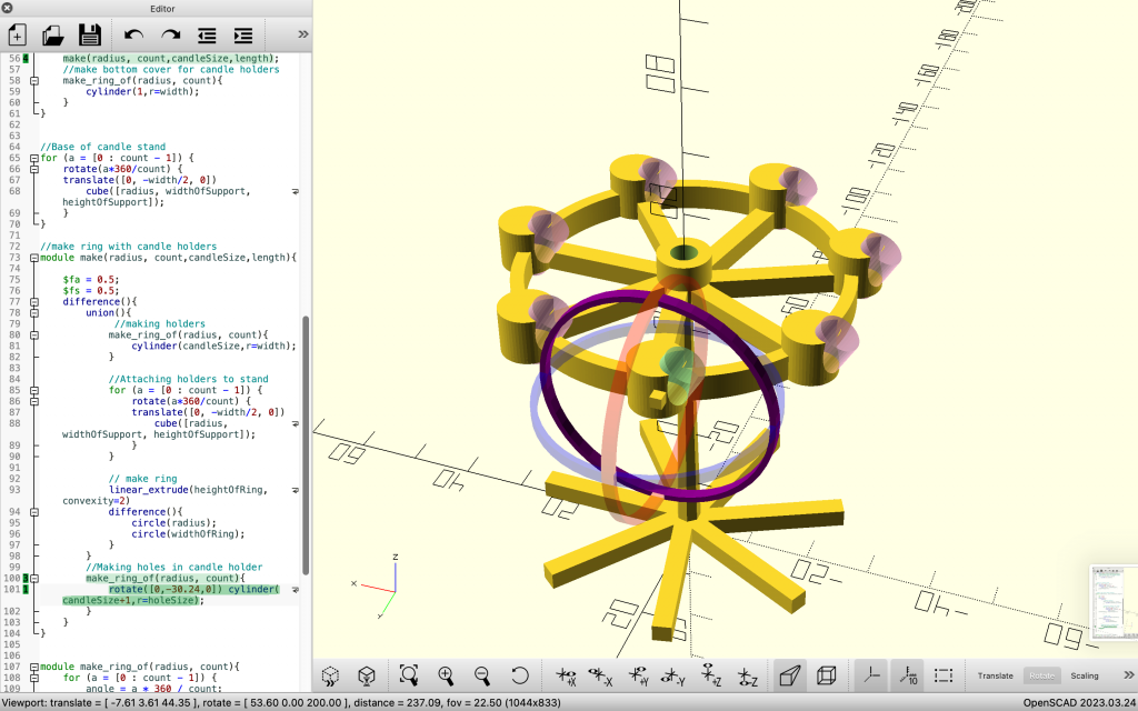
You can click anywhere on the view and drag and drop to perform the edit. The system will automatically add or modify a pre-existing statement in the code while updating the 3D view.
Limitations
This is a project in development and as such it has some limitations.
Only one-file models
Currently, interactive features ONLY work with models scripted in one file
Constraints editing not supported… yet
Currently, the system does not support making edits on statements with variable-based constraints. When trying to edit one, the system will not perform any action.
Previous versions
For checking previous versions visit this link.
Facilitating the Parametric Definition of Geometric Properties in Programming-Based CAD
We present the source code of our modified version of OpenSCAD that allows users to extract parametric definitions of geometric properties form the view to define new elements in the code.
Getting started
Currently, only the source code is available at this link. To install, please follow the instructions on the OpenSCAD website using our source code.
This project is currently supported only for MacOS. You can download the latest binaries of our version on this link. Also, it works well in ONE file models.
Contact us
The system is under development and it is not stable. Please contact us to johannavila@cmail.carleton.ca if you need assistance.